Creating a ROM circuit using MultiSim
A basic ROM can be implemented by using a set of gates and some LEDs for the output.In the following example a ROM which is used to store a string as an array is implemented.As an example,I have stored the word 'python' in the circuit.
What you give in as input is the array index and what you get as output is is the contents in the index location given as input.
The first step in designing the ROM is to convert the string into numbers,For this I have used the corresponding alphabet numbers(1 for a,2 for b and so on).So python becomes:
Char Num Binary Index
p 16 1 0 0 0 0 0
y 25 1 1 0 0 1 1
t 20 1 0 1 0 0 2
h 8 0 1 0 0 0 3
o 15 0 1 1 1 1 4
n 14 0 1 1 1 0 5
Note that using ASCII codes gives you more options such as Capitals,special characters etc.I just intended a simple implementation of ROM.
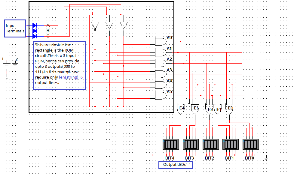
Given below is the circuit of the ROM.From the circuit,it can be analysed that when the input is 000,the line A0 gets activated,ie,the line corresponding to the decimal equivalent of the input turns on.All other lines remain off.
To decide which lines must go into the OR gate,follow these steps:
a)From the table above choose the first column {1 1 1 0 0 0 }.
b)Choose an OR gate with number of terminals = number of 1s in the column.
c)ADD the lines which give output 1.(here lines A0 A1 A2)
d)The output of the OR operation gives the first bit BIT4 of our output.
e)Repeat the above steps to find BIT3 BIT2 BIT1 and BIT0 using corresponding columns.
f)Connect the output terminals to and LED or Multimeter to "see" the output.

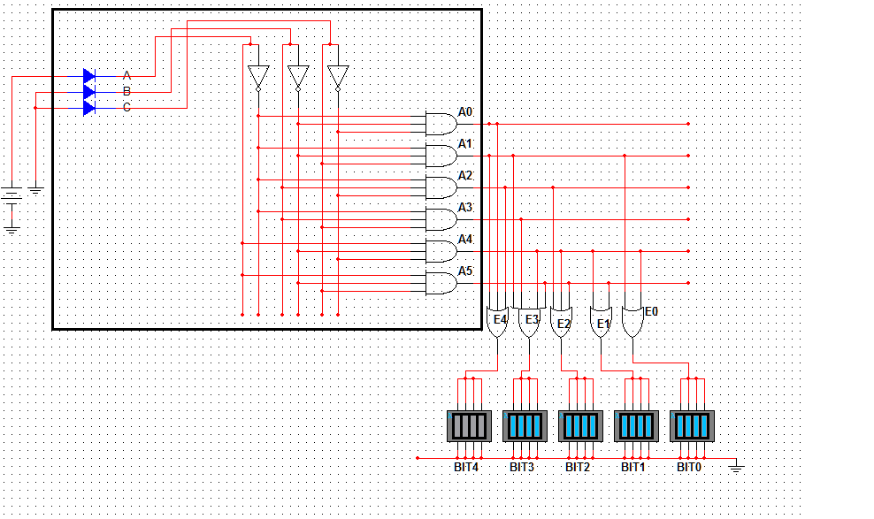
Here is a sample run.Suppose we give the input as 100,ie index four of the word python = 'o'.
You can see that the LEDs show an output of 01111=15='o'.
This setup can be used to store any sort of binary data in hardware.The input terminals may be increased or decreased as per requirement.
What you give in as input is the array index and what you get as output is is the contents in the index location given as input.
The first step in designing the ROM is to convert the string into numbers,For this I have used the corresponding alphabet numbers(1 for a,2 for b and so on).So python becomes:
p 16 1 0 0 0 0 0
y 25 1 1 0 0 1 1
t 20 1 0 1 0 0 2
h 8 0 1 0 0 0 3
o 15 0 1 1 1 1 4
n 14 0 1 1 1 0 5
Note that using ASCII codes gives you more options such as Capitals,special characters etc.I just intended a simple implementation of ROM.
Given below is the circuit of the ROM.From the circuit,it can be analysed that when the input is 000,the line A0 gets activated,ie,the line corresponding to the decimal equivalent of the input turns on.All other lines remain off.
To decide which lines must go into the OR gate,follow these steps:
a)From the table above choose the first column {1 1 1 0 0 0 }.
b)Choose an OR gate with number of terminals = number of 1s in the column.
c)ADD the lines which give output 1.(here lines A0 A1 A2)
d)The output of the OR operation gives the first bit BIT4 of our output.
e)Repeat the above steps to find BIT3 BIT2 BIT1 and BIT0 using corresponding columns.
f)Connect the output terminals to and LED or Multimeter to "see" the output.
Here is a sample run.Suppose we give the input as 100,ie index four of the word python = 'o'.
 |
| *Circuits using Multisim |
You can see that the LEDs show an output of 01111=15='o'.
This setup can be used to store any sort of binary data in hardware.The input terminals may be increased or decreased as per requirement.